Harbor Freight Tools 95607 User Manual - Page 11
Assembly Instructions Continued
 |
View all Harbor Freight Tools 95607 manuals
Add to My Manuals
Save this manual to your list of manuals |
Page 11 highlights
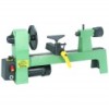
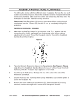
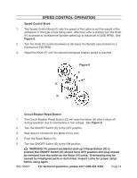
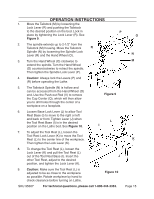
Assembly Instructions (continued) The Mini Lathe comes with two different sized Faceplates (A). Use the one best suited to size of the workpiece. Mount the workpiece onto the Faceplate with wood screws (not provided). Make sure the screws are not so long that they enter the workspace of where the material is being removed. Please note: Both Faceplates (A) have an open center. When cutting through a workpiece from the Tailstock (M), the drill bit can go completely through the workpiece. Installing or removing a faceplate: 1. Make sure the ON/OFF Switch (E) of the tool is in its "OFF" position, the key removed and the tool is unplugged from its electrical outlet before making adjustments to the tool. Thread the Faceplate (A) onto the end the Headstock Spindle (B) and hand tighten. Figure 2 A S V 2. Place the Wrench (S) over the flats on the Faceplate (A). See Figure 2. Please note: Since the Headstock Spindle (B) is belt driven, it will turn freely if not held stationary while the Faceplate (A) is tightened or loosened. 3. Insert the tip of the Push-out Rod (V) into one of the slots in the side of the Headstock Spindle (B). 4. Grip the Push-out Rod (V) firmly while turning the Wrench (S) to either tighten or loosen the Faceplate (A). 5. Remove the Push-out Rod (V) and Wrench (S). If the Faceplate (A) is being removed, continue turning it until it comes off of the spindle threads. SKU 95607 For technical questions, please call 1-800-444-3353. Page 11
-
 1
1 -
2
-
3
-
4
-
5
-
 6
6 -
 7
7 -
 8
8 -
 9
9 -
 10
10 -
 11
11 -
 12
12 -
 13
13 -
 14
14 -
 15
15 -
 16
16 -
17
-
18
-
19
-
20
 |
 |
